Difference between revisions of "Routes"
(Created page with "'''ROUTES''' In this tab you can configure and manage the routes to all the destinations you offer. <center></center> <center>''Figure 29. Routes Window.''</center> Fi...") |
|||
| (7 intermediate revisions by the same user not shown) | |||
| Line 1: | Line 1: | ||
| − | ''' | + | Click Here to return to the main Screen: '''[[Routing |Back]]''' |
| Line 5: | Line 5: | ||
| − | <center></center> | + | <center>[[Image:Figure29.png]]</center> |
| Line 44: | Line 44: | ||
# Click âAddâ. The following window will appear: | # Click âAddâ. The following window will appear: | ||
| − | <center>[[Image:]]</center> | + | <center>[[Image:Figure30.png]]</center> |
| Line 58: | Line 58: | ||
# When you click âSaveâ, you will be redirected to the following window: | # When you click âSaveâ, you will be redirected to the following window: | ||
| − | <center></center> | + | <center>[[Image:Figure31.png]]</center> |
| Line 66: | Line 66: | ||
# Drag the Resource Groups that will compose your route from the list on the left and drop them under the route you are configuring. Figure 32 shows an example where the automatic routing module is routing part of the traffic, according to the percentage it is given. | # Drag the Resource Groups that will compose your route from the list on the left and drop them under the route you are configuring. Figure 32 shows an example where the automatic routing module is routing part of the traffic, according to the percentage it is given. | ||
| − | <center></center> | + | <center>[[Image:Figure32.png]]</center> |
| Line 76: | Line 76: | ||
# If working under the percentage scheme, you can edit the percentage of calls the Resource Groups are going to manage (see Figure 33). | # If working under the percentage scheme, you can edit the percentage of calls the Resource Groups are going to manage (see Figure 33). | ||
| − | <center></center> | + | <center>[[Image:Figure33.png]]</center> |
| Line 85: | Line 85: | ||
| − | <center></center> | + | <center>[[Image:Figure34.png]]</center> |
| Line 103: | Line 103: | ||
# Click âEditâ. The following window will appear: | # Click âEditâ. The following window will appear: | ||
| − | <center></center> | + | <center>[[Image:Figure35.png]]</center> |
| Line 115: | Line 115: | ||
# Click on [[Image:]] to display the list of Partitions, RG and clients affected by the edition (Figure 36). | # Click on [[Image:]] to display the list of Partitions, RG and clients affected by the edition (Figure 36). | ||
| − | <center>[[Image:]]</center> | + | <center>[[Image:Figure36.png]]</center> |
| Line 130: | Line 130: | ||
# Click on âReplace RGâ. The following window will appear: | # Click on âReplace RGâ. The following window will appear: | ||
| − | <center>[[Image:]]</center> | + | <center>[[Image:Figure37.png]]</center> |
| Line 139: | Line 139: | ||
# Click âApplyâ and confirm the changes by clicking âSaveâ. | # Click âApplyâ and confirm the changes by clicking âSaveâ. | ||
| − | |||
| − | |||
| − | |||
| − | |||
| − | |||
| − | |||
| − | |||
| − | |||
| − | |||
| − | |||
| − | |||
| − | |||
| − | |||
| − | |||
| − | |||
| − | |||
| − | |||
| − | |||
| − | |||
| − | |||
| − | |||
| − | |||
| − | |||
| − | |||
| − | |||
| − | |||
| − | |||
| − | |||
| − | |||
| − | |||
| − | |||
| − | |||
| − | |||
| − | |||
| − | |||
| − | |||
| − | |||
| − | |||
| − | |||
| − | |||
| − | |||
| − | |||
| − | |||
| − | |||
| − | |||
| − | |||
| − | |||
| − | |||
| − | |||
| − | |||
| − | |||
| − | |||
| − | |||
| − | |||
| − | |||
| − | |||
| − | |||
| − | |||
| − | |||
| − | |||
| − | |||
| − | |||
| − | |||
| − | |||
| − | |||
| − | |||
| − | |||
| − | |||
| − | |||
| − | |||
Latest revision as of 16:15, 28 January 2014
Click Here to return to the main Screen: Back
In this tab you can configure and manage the routes to all the destinations you offer.
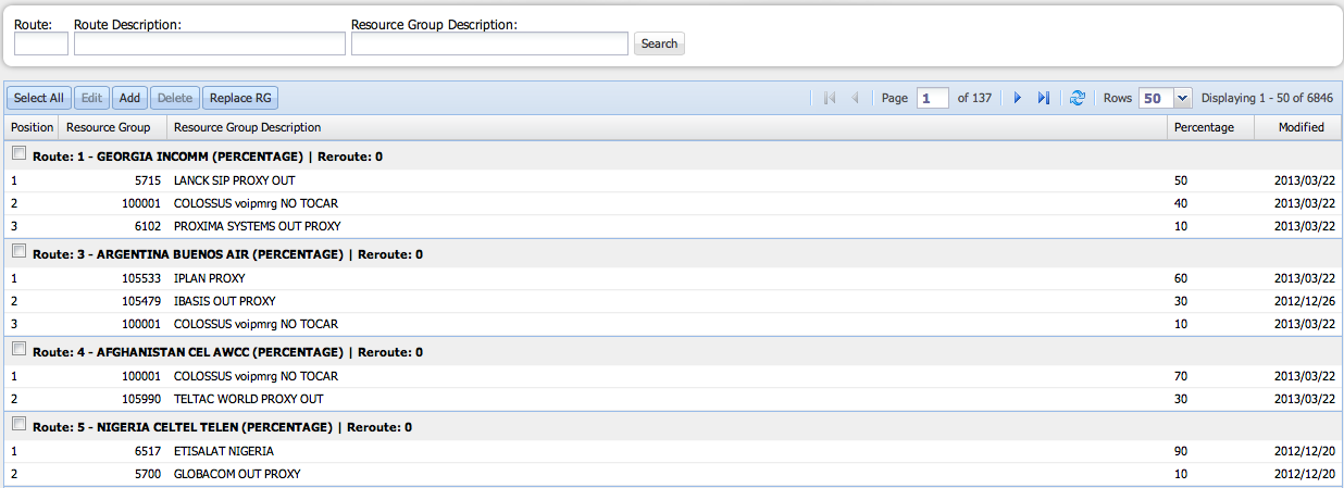
Figure 29 shows the Routes Window. Following is an explanation of each field of the table:
- Position
This field denotes the order in the RG Out to be followed when a provider does not connect a call. The call is re-routed to the next RG Out of the list. This field applies when the Least Cost Routing scheme is used.
- Resource Group
These are the Resource Group IDs that compose the route.
- Resource Group Description
This field contains the name of the carrier and other details of the Resource Group.
- Percentage
If the route works under the percentage scheme, this field denotes the percentage of traffic managed per Resource Group.
- Modified
The system fills this field automatically with the date of the last modification of the route.
To create a route:
- Click âAddâ. The following window will appear:
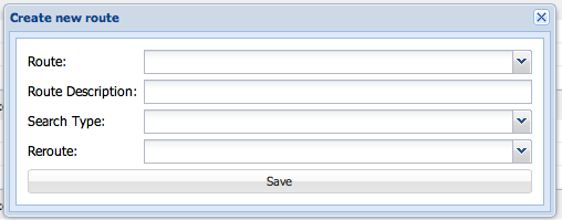
- Enter the Route ID or select it from a drop - down list, and enter the Route Description.
- Select the Search Type and the Reroute value from a drop âdown list. Reroute means the disconnection cause code to be used to reroute within the same route.
- Click âSaveâ to confirm the changes or close the window to discard them.
- When you click âSaveâ, you will be redirected to the following window:
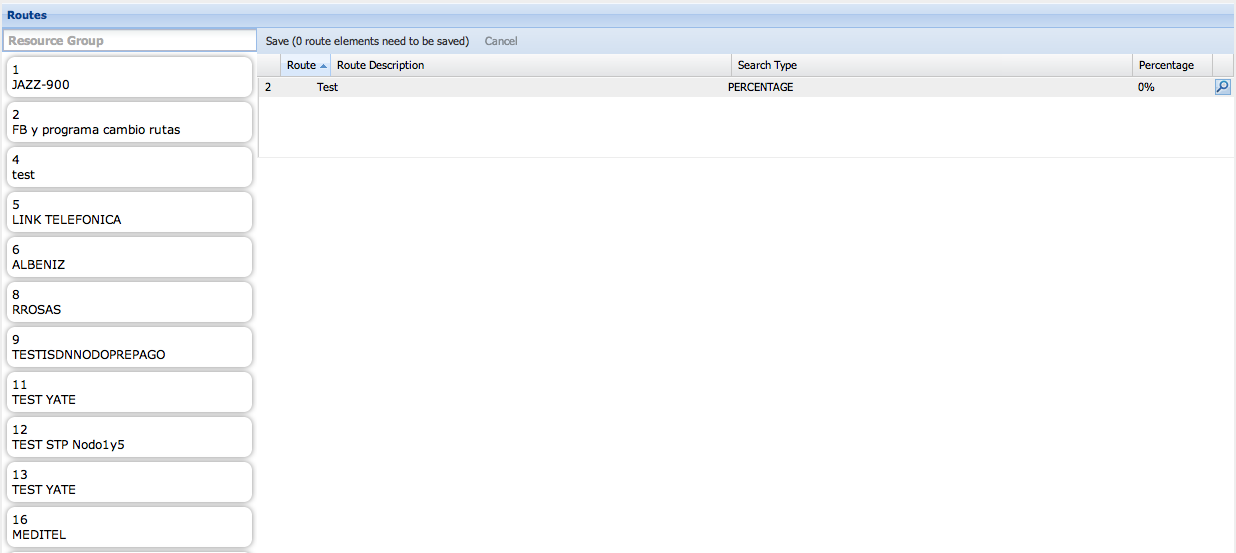
- Drag the Resource Groups that will compose your route from the list on the left and drop them under the route you are configuring. Figure 32 shows an example where the automatic routing module is routing part of the traffic, according to the percentage it is given.
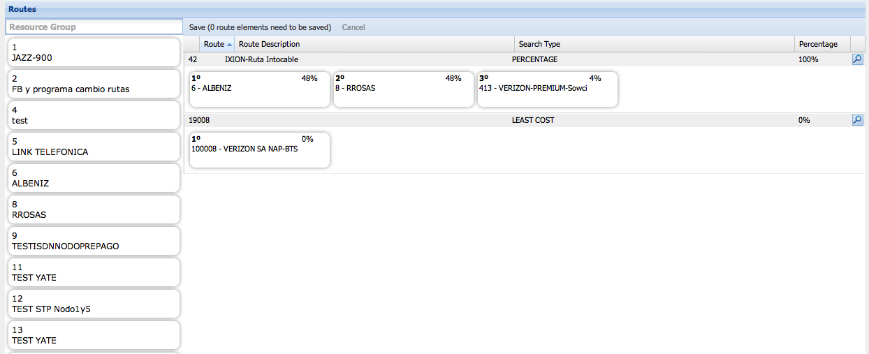
- You can re-order the Resource Groups by dragging them and dropping them in another position. This is useful to determine the position of the RG Out when working under Least Cost Route scheme.
- If working under the percentage scheme, you can edit the percentage of calls the Resource Groups are going to manage (see Figure 33).
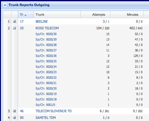
You can track the percentage distribution in the cell under Percentage (Figure 34).

- Click âSaveâ to confirm the changes.
- To go back to the Routes list, click on Route in the Main Menu bar.
To delete an existing route select the check box next to the route and click âDeleteâ. A confirmation window will appear.
To edit an existing route:
- Click âEditâ. The following window will appear:

- You can add new Resource Groups or remove the existing ones by dragging them and dropping them back on the list to the left.
- You can edit the Search Type and percentage of each Resource Group. You can also change the order of the Resource Groups.
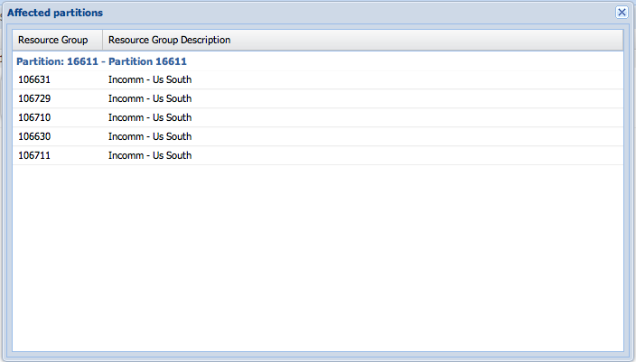
- Click on [[Image:]] to display the list of Partitions, RG and clients affected by the edition (Figure 36).
- Click âSaveâ to confirm the changes.
- Go back to the Routes List.
To replace a Resource Group in the routes it takes part:
- Click on âReplace RGâ. The following window will appear:

- Enter the Resource Group Description you want to replace and the new description.
- Click âApplyâ and confirm the changes by clicking âSaveâ.